The Ultra Solar Controller SC-3 from Australian Energy Systems provides intelligent automated control for solar pool heating systems. This guide covers installation, setup, and operation for both standalone and integrated pool heating configurations.
Product Overview
What’s Included
Your SC-3 package contains:
- Ultra Solar SC-3 Controller unit
- Pool temperature sensor with 3.5m cable
- Roof temperature sensor with 20m cable
- Sensor grommet for pool installation
- DIN rail and screw kit for wall mounting
- Instruction manual
Key Features
Intelligent Control: The SC-3 continuously monitors pool and roof temperatures, automatically operating the solar pump only when heating is beneficial. The system purges fresh pool water every 3 hours to maintain accurate temperature readings.
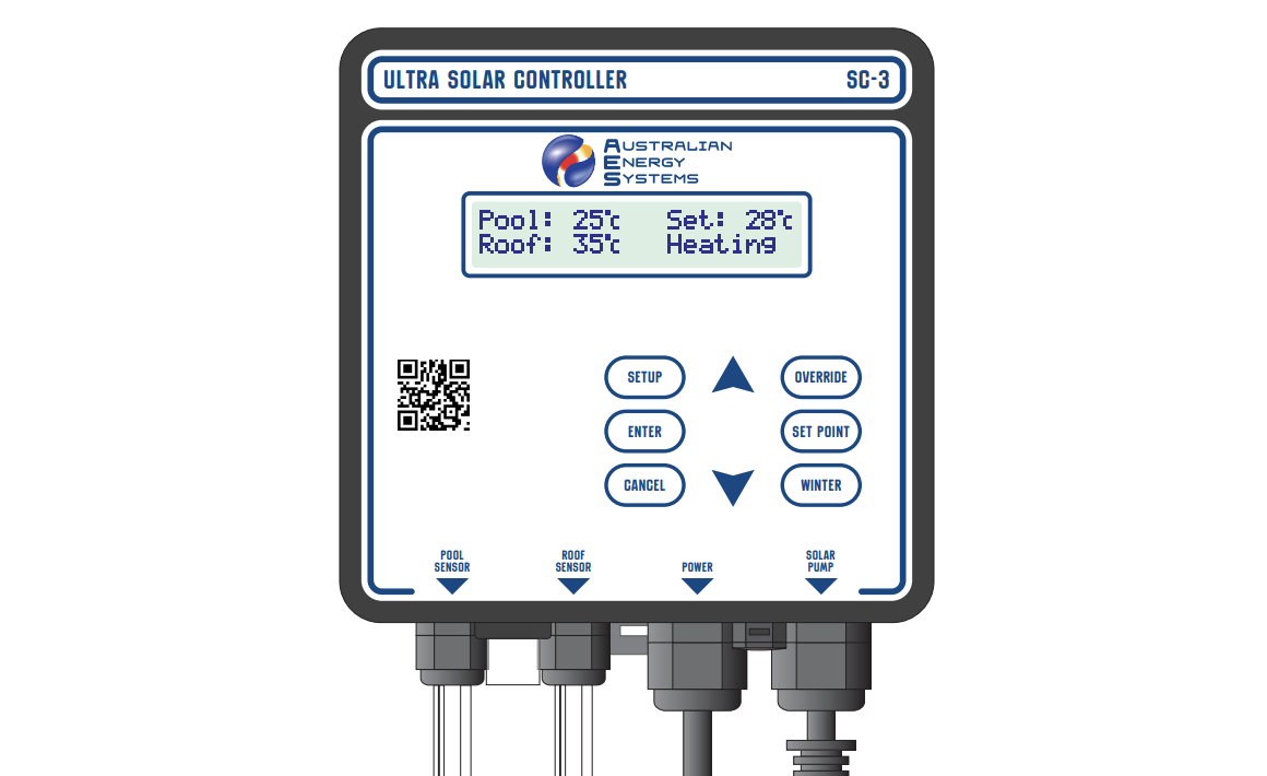
User-Friendly Interface: Plain text LCD display with simple button controls provides clear information about pool temperature, roof temperature, set point, and system status.
Weather Resistant Design: IP-rated enclosure with vented construction prevents internal condensation. Built-in 10A circuit breaker provides overload protection.
Flexible Configuration: Supports both standalone solar systems and integration with existing pool equipment, including sanitisers and filtration pumps.
Understanding Your SC-3
Display Information
The LCD screen shows four key pieces of information:
Pool Temperature: Current water temperature measured by the pool sensor in the suction line.
Roof Temperature: Current temperature from the roof sensor mounted alongside solar collectors. This measures heat absorption in a black tube, not air temperature. In hot climates, roof temperatures can exceed 70°C.
Set Point: Your target pool temperature (default 28°C). The system maintains temperature within 1°C of this setting.
Status Messages: Real-time system information, including:
- Heating – Solar pump running to warm the pool (pool below set point)
- Cooling – Solar pump running to cool the pool at night (pool above set point)
- Purging – Running the pump for 5 minutes to refresh the pool temperature reading
- Over: On – Override mode forcing pump to run regardless of temperatures
- Over: Off – Override mode preventing pump operation
- Winter – Winter mode with daily 5-minute midday operation
- Overheat – Pool reached 40°C, pump disabled for safety
- No Flow – Optional flow switch detected no water circulation
Control Buttons
SETUP – Access advanced settings, including start/stop times, cooling mode, temperature calibration, and clock setting
ENTER – Confirm and save setting changes
CANCEL – Exit menus without saving changes
SET POINT – Quickly adjust target pool temperature (20-40°C range)
OVERRIDE – Manually control pump operation (Auto/On/Off modes)
WINTER – Toggle between summer heating and winter maintenance modes
Up/Down Arrows (▲▼) – Navigate menus and adjust values
Installation
Safety Warnings
Critical: Read all instructions before beginning installation. Although the SC-3 has a weather-resistant design, service life extends significantly when protected from direct sunlight and rain. Environmental wear is not covered by warranty.
Keep the power cord visible and accessible. Never bury cables. Prevent grass and weeds from growing around the unit to avoid damage from garden equipment. Replace any damaged cables immediately to prevent electric shock.
Electrical Safety: Unplug power before inspecting or working on equipment. Only authorized service agents should open the unit – internal access may cause electric shock resulting in injury or death.
Controller Unit Installation
Location Selection:
Choose a mounting position that protects the unit from direct weather exposure. The SC-3 must be mounted vertically with cables at the bottom for proper weather resistance. Water ingress from incorrect mounting voids warranty coverage.
Verify the pool sensor cable (3.5m) reaches comfortably from the suction line to the controller. Confirm the roof sensor cable (20m) spans from the solar collectors to the controller without strain. Ensure the solar pump power lead reaches the SC-3 outlet socket, which must hang downward for weather protection.
Mounting Procedure:
Install the provided DIN rail mounting plate level on your chosen surface using the supplied screws and wall plugs. Hook the SC-3 mounting clip onto the top rail of the mounting plate. Pull the mounting clip down while pushing the unit against the bottom rail. The clip locks automatically behind the bottom rail.
To remove, pull the mounting clip downward to release from the rail.
Pool Temperature Sensor Installation
Location: Install the pool sensor in the suction line before the solar pump. The sensor works in any orientation but must be installed in pipe, not thicker-walled PVC fittings.
Installation Steps:
Using a 12mm or 1/2″ drill bit, create a hole in the selected pipe location. Spade or wood bits work better than HSS metal bits. If using HSS metal bits, run the drill in reverse to prevent pipe damage.
Remove all burrs from the drilled hole. Push the supplied rubber grommet into the hole, ensuring even seating all around. Insert the pool temperature sensor fully through the grommet.
Connect the sensor’s male and female 4mm bullet connectors to the POOL SENSOR input terminals on the SC-3.
Roof Temperature Sensor Installation
Location: Mount the roof sensor alongside the solar collector panels at the same angle to the sun. Alternatively, any surface matching the collector angle works. Ensure the sensor won’t be shaded by trees, buildings, or structures when collectors receive sunlight. Watch for young plantings that may create future shade.
Cable Routing:
Run the 20m cable from the roof sensor back to the SC-3. Where underground routing is necessary, use an electrical conduit. Remove bullet crimp connectors to thread cable through conduit, then re-fit new 4mm bullet crimps afterwards.
Trim excess cable if desired, fitting new bullet crimps after cutting. Connect male and female bullet connectors to the ROOF SENSOR input terminals on the SC-3.
Power and Plumbing Connections
Standalone System (Separate Solar Provisions):
This configuration uses dedicated solar plumbing separate from the main pool circulation.
Electrical: Connect the SC-3 power lead to a suitable 10A rated, weather-resistant power outlet. Plug the solar pump into the SOLAR PUMP outlet socket on the SC-3.
Plumbing: Draw cold water from the pool through the dedicated solar pump. Pump this water to the roof-mounted solar collectors. Return heated water to the pool through separate solar return plumbing.
Integrated System (Shared Filtration Provisions):
This configuration integrates solar heating with existing pool equipment.
Electrical Power Chain:
- Connect the sanitiser system power lead to 10A rated, weather-resistant outlet
- Plug the SC-3 power lead into the sanitiser’s pool pump outlet socket
- Connect the pool pump power lead into SC-3’s piggyback power socket
- Plug the solar pump into SC-3’s SOLAR PUMP outlet
Plumbing Configuration:
Tap the solar pump suction from the pool return line after the filter, before the heated water return from collectors. Route heated water from collectors back into the pool return line after the solar pump takeoff, before the sanitiser.
Critical: Water flow for solar heating must always precede any sanitisation system. This prevents damage to solar collectors from high sanitiser concentrations.
Basic Operation
How the SC-3 Works
The controller operates automatically with minimal adjustment required after installation. Default settings work well for most applications.
Default Settings:
- Set point: 28.0°C
- Control band: 1.0°C
- Heating differential: 5.0°C
- Start time: 7:00 am
- Stop time: 7:00 pm (19:00)
The solar pump activates when the pool temperature falls below 27.0°C (1°C below the set point), running until the water reaches 28.0°C. For heating, the system only operates when the roof temperature exceeds the pool temperature by at least 5°C. For cooling, the roof must be at least 5°C cooler than the pool.
The controller purges the system every 3 hours, running fresh pool water through sensors to verify accurate temperature readings. The final daily purge occurs at the programmed stop time.
Adjusting Set Point
Press the SET POINT button. The current target temperature displays on screen.
Use ▲ the ▼ buttons to adjust between 20°C and 40°C. Press ENTER to save the new setting, or CANCEL to exit without changes.
Recommended settings:
- 26-28°C for comfortable recreational swimming
- 28-30°C for warmer, spa-like temperatures
- 24-26°C for fitness/lap swimming
Override Function
Override mode allows manual control, overriding automatic temperature-based operation.
Press the OVERRIDE button. Use ▲ and ▼ select:
AUTO – Normal automatic heating control based on temperatures
ON – Forces solar pump to run regardless of pool and roof temperatures. Useful for system testing or extra heating before events. The pump stops if the pool reaches 40°C for safety. The system reverts to AUTO at programmed stop time.
OFF – Prevents solar pump operation even when heating is beneficial. Useful for maintenance or when pool will be unused. System reverts to AUTO at stop time.
Press ENTER to activate the selected mode, or CANCEL to exit without changes.
Winter Mode
Winter mode stops heating when insufficient solar energy is available during colder months, while maintaining system health.
Activating Winter Mode: Press the WINTER button once. The display confirms winter mode activation. The solar pump runs for 5 minutes at midday daily, preserving seals and preventing water stagnation without active heating.
Returning to Summer Mode: Press WINTER again when swimming season returns. Normal solar heating control resumes immediately.
Cooling Mode
In tropical climates, the SC-3 can cool excessively warm pools overnight.
Activating Cooling Mode:
Press SETUP. Use ▲ and ▼ to navigate until “Cooling Mode” appears with the current setting shown in brackets (default: OFF).
Press ENTER to change the setting. Select ON using ▲ the ▼ buttons. Press ENTER to save, or CANCEL to exit.
When cooling mode is active, the controller heats during the day and cools at night as needed. Consider reducing your set point and adjusting the stop time to a later evening or 24-hour operation for effective cooling.
Advanced Settings
Start Time
The earliest time each day the solar pump may operate. The default is 7:00 am, preventing early morning noise disturbance.
Adjusting Start Time:
Press SETUP. Navigate with ▲ and ▼ until “Start Time” displays with the current setting in brackets.
Press ENTER. Use ▲ and ▼ to set the desired start time (range: 6:00 am to 6:00 pm). The late allowable start time accommodates installations focused on nighttime cooling.
Press ENTER to save, or CANCEL to exit.
Stop Time
The latest time each day the solar pump may operate. Default is 7:00 pm (19:00).
Adjusting Stop Time:
Press SETUP. Navigate to “Stop Time” showing the current setting.
Press ENTER. Set the desired stop time with ▲ and ▼. For cooling mode, set this to late evening or after midnight – the software handles times past midnight correctly.
For a 24-hour operation allowing heating and cooling as needed, set the stop time identical to the start time.
Press ENTER to save, or CANCEL to exit.
Setting the Clock
The SC-3 uses a 24-hour time format.
Press SETUP. Navigate to “Set Clock” showing current time in brackets.
Press ENTER to begin clock setting. Use ▲ and ▼ to set hours (0-23). Hold buttons for rapid scrolling. Press ENTER to confirm hours.
Use ▲ and ▼ to set minutes. Press ENTER to confirm minutes. The controller returns to normal operation.
The clock has a supercapacitor backup, maintaining correct time for several days during power outages.
Temperature Units
Switch between Celsius and Fahrenheit display.
Press SETUP. Navigate to “Temp Units” showing current setting (default: Celsius).
Press ENTER. Select °C or °F with ▲ and ▼. Press ENTER to save, or CANCEL to exit.
Temperature Calibration
The SC-3 arrives pre-calibrated for the supplied sensors. Recalibration is only needed when replacing sensors. The procedure is identical for pool and roof sensors.
Preparation: If calibrating the pool sensor, first select Override:Off to prevent pump operation during sensor removal. Place the sensor to be calibrated in a beaker of water alongside an accurate reference thermometer. Stir the water to ensure an even temperature.
Calibration Procedure:
Press SETUP. Navigate to “Calibrate Pool Temp” or “Calibrate Roof Temp” as needed.
Press ENTER. The calibration screen displays:
- Raw sensor reading without calibration
- Calibrated reading with current adjustment
- Offset adjustment in degrees
- Final display value rounded to 1°C
Use ▲ and ▼ to adjust the calibrated value to match your reference thermometer.
Press ENTER to save calibration, or CANCEL to exit without changes. The controller returns to normal display in Override: Off mode. Reinstall the pool sensor before switching back to AUTO.
Troubleshooting
Status Messages
Temperature Shows “Low”:
The sensor shows “Low” when measuring 0°C or below, when the sensor cable has been cut (open circuit), or when the sensor itself has failed, causing false low readings.
Ifthe actual temperature is at or below freezing, no action is needed. Otherwise, inspect cables for damage and repair cut wires. Replace faulty sensors if problems persist.
Temperature Shows “Short”:
Short circuit detected in one or both temperature sensors. The SC-3 cannot identify which sensor is faulty.
Disconnect each sensor individually to isolate the problem sensor. Replace the faulty unit.
Hardware Fail Messages:
“Clock Fail” indicates the controller cannot communicate with the internal clock chip. Press CANCEL to restart, or power off for 5 seconds then restart. Return for repair if the problem continues.
Version information (e.g., “v1.0”) displays each time the SC-3 powers on. Note this version number when contacting technical support.
Circuit Breaker Trips
The built-in 10A circuit breaker protects against power overload. Common causes include:
- Solar pump rated above 10A
- Excessive start-up current surge from the pump
- Faulty pump components (damaged capacitors)
- Internal controller fault
Resetting the Circuit Breaker:
- Disconnect SC-3 from the power outlet
- Press the black circuit breaker button until it clicks
- Reconnect SC-3 to power
If the breaker continues tripping, identify and correct the underlying cause before continued operation.
Warranty Coverage
Australian Energy Systems provides a 3-year limited warranty on the Ultra Solar Controller SC-3 and a 1-year warranty on temperature sensors.
The warranty covers defects in materials and workmanship under normal use. Return faulty units freight prepaid for free repair and return.
Warranty Exclusions
The warranty does not cover:
- Improper installation or failure to follow operating instructions
- Damage from accidents, adverse environmental conditions, tampering, abuse, or negligence
- Weather damage from improper mounting (unit must be vertical with cables downward)
- Damage from excessive pool chemical concentrations
- Shipping damage
- Modifications or repairs by unauthorised persons
- Incidental or consequential damages
Warranty Requirements
Warranty applies only to original purchasers. Proof of purchase is required for all claims. Installation must comply with safety regulations and local electrical codes.