The TDI (Top Discharge Inverter) Full Inverter Swimming Pool Heat Pump represents advanced pool heating technology using R32 refrigerant. This guide covers installation, operation, and maintenance for the 13kW, 20kW, and 26kW models.
Product Overview
Available Models and Specifications
| Model | TDI 13 | TDI 20 | TDI 26 |
| Recommended Pool Volume | 40-53m³ | 64-85m³ | 78-104m³ |
| Heating Capacity | 12.56kW | 20.41kW | 26.21kW |
| Max Power Draw | 3.2kW | 4.7kW | 6.33kW |
| Max Current | 12A | 18A | 24A |
| Water Flow Required | 75 L/min | 110 L/min | 145 L/min |
| Refrigerant (R32) | 1.0kg | 1.45kg | 1.8kg |
| Net Weight | 49kg | 62kg | 72kg |
| Noise at 1m | 42-53 dB(A) | 45-55 dB(A) | 45-57 dB(A) |
Key Features
Advanced Technology: Full DC inverter system with Mitsubishi twin rotary compressor provides variable speed operation for maximum efficiency. The unit achieves COP ratings up to 14.65 in optimal conditions (26°C ambient, 80% humidity).
Temperature Range: Operates in heating mode from 15°C to 40°C ambient, cooling mode from 8°C to 28°C ambient, with an overall operating range of -10°C to 43°C.
Smart Controls: Features a digital touch panel with Wi-Fi connectivity through the Smart Life app, allowing remote monitoring and control from your smartphone.
Installation Requirements
What’s Included
Your TDI heat pump package contains the main unit, up pipe temperature sensor, down pipe sensor, drain connector, drain pipe, rubber mounting blankets, protective hood, and installation manual.
Tools Needed
- Drill with hammer action capability
- 6mm masonry drill bit (for wall mounting)
- 12.5mm drill bit (for sensor installation)
- P-2 Phillips head screwdriver
- Power cable suitable for the unit capacity
- PVC piping, primer, and solvent
- Mounting hardware
Location Requirements
Critical Placement Guidelines:
The heat pump must be positioned at least 3.5 metres from the pool zone for electrical safety compliance. Install within 1.5 metres of your pool pump for optimal hydraulic efficiency. Mount the unit upright on a level, stable concrete surface 1 metre above ground level.
Clearance Requirements:
Maintain 500mm clear space on the sides and rear of the unit. Leave at least 1 metre clearance in front of the top discharge air outlet. Ensure adequate ventilation above the unit with no obstructions.
Environmental Considerations:
Avoid locations exposed to oil, flammable gases, corrosive products, or high-frequency equipment. Don’t install near roads where mud splashes could occur. Position away from windows and noise-sensitive areas. Keep out of reach of children.
Mounting the Unit
Foundation: The mounting surface must support the unit’s weight with a minimum capacity of 21g/mm². Use either the sheet metal foot mounting or the rubber blanket mounting method provided.
Drainage: Install the supplied drainage tube and connector at the bottom outlet to handle condensation water. The unit produces condensation during operation, so proper drainage is essential.
Installing Temperature Sensors
Up Pipe Sensor (Solar Panel Return):
Using the 12.5mm drill bit, create a hole in the pipe returning from solar panels. Insert the rubber grommet first, then push the temperature sensor through until firmly seated. Connect the sensor cable to the controller using the red bullet connectors provided.
Down Pipe Sensor (Pool Water):
Follow the same procedure for the pipe leading from the pool. Ensure both sensors are securely installed, and connections are watertight.
Plumbing Configuration
Important: The inlet and outlet unions cannot support the weight of flexible hoses. Connect only with rigid PVC piping to prevent damage to the internal titanium heat exchanger.
Keep the total pipe length between the pool and heat pump under 10 metres for optimal heating efficiency. Install isolation valves, bypass system, and drainage valves as shown in the installation diagrams.
System Configurations:
Stand-Alone System: The heat pump operates independently with its own dedicated pump. Plug the controller directly into a power outlet, then plug the solar pump into the base of the controller.
Integrated System: Works with existing pool equipment. Connect the chlorinator to the power outlet, the solar controller’s grey plug to the chlorinator, the filter pump to the grey connector, and the solar pump to the controller base.
Electrical Installation
Critical Requirements: This unit must be electrically connected following AS/NZS 3000 Wiring Rules by a licensed electrician.
The general electricity supply must include a 30mA differential switch (safety switch). Install an appropriately rated D-curve circuit breaker. Use outdoor-rated cable with correct specifications:
- TDI 13: 3G 2.5mm² (AWG 14)
- TDI 20: 3G 2.5mm² (AWG 12)
- TDI 26: 3G 4.0mm² (AWG 10)
Ensure proper earthing connections. For public installations, an emergency stop button is mandatory near the heat pump.
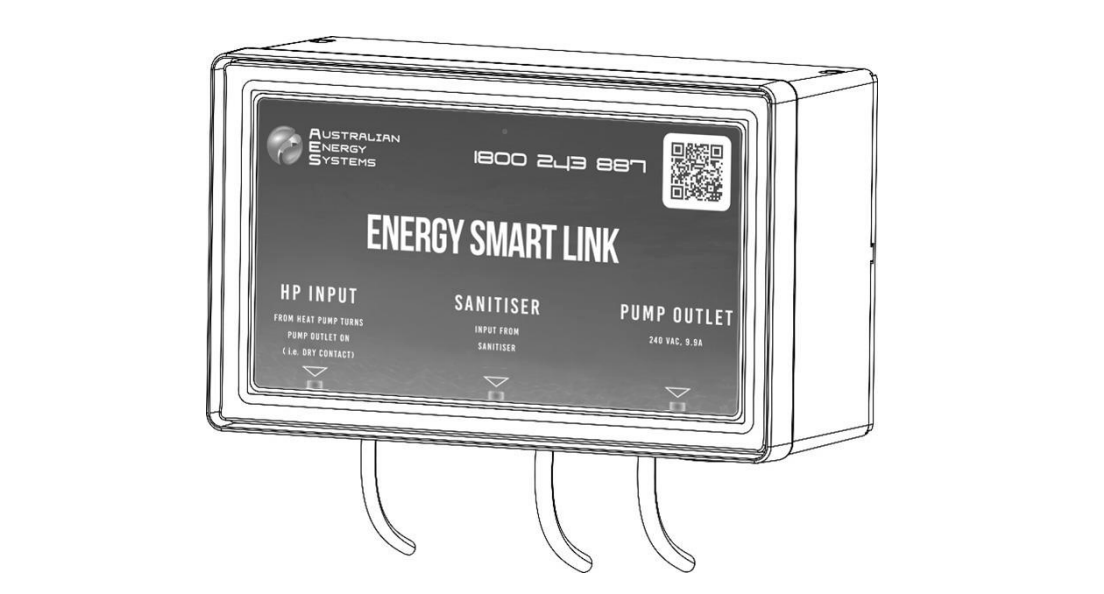
Third-Party Controller Integration
Adding a third-party pool automation controller is highly recommended. Connect to the L1 and N1 terminals on the power block. This allows integration without removing power plugs from pool pumps, which may void their warranty.
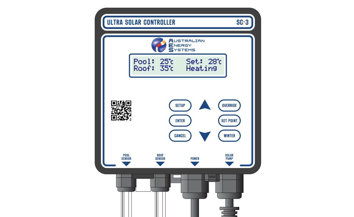
Controller Operation
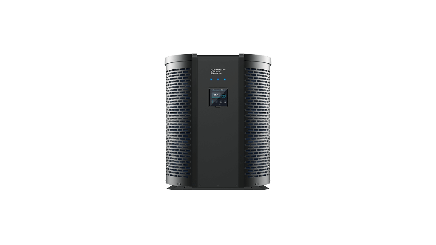
Control Panel Features
The circular digital touch panel displays current temperature, target temperature, operating mode, and system status. LED indicators show heating/cooling mode, Wi-Fi status, timer settings, and frequency mode (Boost/Smart/Silent).
Button Functions:
Mode Button 1 (M): Switches between Cooling, Heating, and Auto modes
Mode Button 2 (fan icon): Cycles through Boost, Smart, and Silent frequency modes
Up/Down Arrows: Adjust target temperature in 1°C increments (range 20-40°C for heating)
Power Button: Short press for on/off; long press (3 seconds) locks/unlocks the screen
Basic Operation
Starting the System: Press the power button. The display shows the current water temperature and allows you to set your desired target temperature.
Setting Temperature: Press up or down arrows to enter temperature setting mode. The temperature display flashes while adjusting. Set your target, then press the power button to confirm, or wait 5 seconds for automatic confirmation.
Mode Selection: Choose your operating mode based on needs. Heating mode warms the pool, cooling mode reduces the temperature on hot days, and auto mode switches automatically based on conditions.
Frequency Modes:
- Silent Mode: Quietest operation, lower capacity, maximum efficiency
- Smart Mode: Balanced performance for typical conditions
- Boost Mode: Maximum heating capacity for rapid temperature increase
Advanced Settings
Clock Setting: Long-press the frequency button for 3 seconds. Use arrows to set hours, press the frequency button to move to minutes, then use arrows to set minutes. Press the frequency button again to save.
Operating Schedule: The controller includes an automatic shutdown timer. The default operation is 8:00 am to 4:00 pm. To adjustthe finish time, press the left arrow and DISPLAY buttons together, then set your preferred shutdown time.
Between finish time and 8:00 am, the display shows “Nop” (not operating) to prevent heat loss during cooler night hours.
Differential Temperature: This advanced setting controls the temperature difference required between solar panels andthe pool before the system activates. Press the right arrow, WINTER, and DISPLAY buttons simultaneously to access. Adjust between 4-6°C for standard conditions.
Timer Programming
The system supports two independent timers with on and off times.
Setting Timers: Long press frequency button and the down arrow for 3 seconds to access the timer menu. Press arrows to cycle through Timer 1 On, Timer 1 Off, Timer 2 On, and Timer 2 Off. For each timer, set hours and minutes, then press the frequency button to save.
Viewing Timers: Use the timer query interface to check current settings without changing them. Long-press to cancel individual timers, or very long press (5 seconds) to cancel all timers at once.
Display Mode
Press the DISPLAY button to cycle through system information without changing settings. The display shows up pipe temperature (U), down pipe temperature (d), last up pipe reading (L), comfort setting (C), clock hours (H), and clock minutes (M).
Winter Mode
Activate winter mode at season’s end to keep water circulating through solar panels without active heating. This prevents stagnation, algae growth, and maintains sensor accuracy. Press the WINTER button to toggle winter mode on and off.
Override Function
Manually run the system regardless of temperature or time restrictions.
1-Hour Override: Press the left and right arrows together simultaneously
4-Hour Override: Press and hold both arrows for 5 seconds
Press both arrows again to cancel the override early. Useful for testing, clearing airlocks, or providing extra heating before events.
Status Query
Long press Mode button for 3 seconds to access detailed system parameters, including compressor frequency, all sensor readings, valve positions, pressure values, drive voltages and currents, and fan speeds. Press arrows to scroll through parameters.
Wi-Fi Setup and Smart Life App
Installing the App
Search “Smart Life” in your app store or scan the QR code in the manual. The app works on both iOS and Android devices.
Registration
New users register by entering their phone number, receiving a verification code, setting a password, creating a home, and adding rooms for device organisation.
Connecting the Heat Pump
EZ Mode (Recommended):
Power on the heat pump. Within 3 minutes, the Wi-Fi icon flashes automatically for network pairing. If needed, manually enter EZ mode by long pressing the up arrow and power button for 3 seconds (Wi-Fi icon flashes rapidly).
Open Smart Life app, tap “+” to add device, select “Large Home Appliances” then “Smart Heat Pump.” Confirm the indicator is flashing rapidly, then tap “Confirm indicator rapidly blink.”
Enter your Wi-Fi password (must match phone’s connected Wi-Fi). The app searches for and registers the heat pump automatically. When complete, the device appears in your app home screen.
AP Mode (Alternative):
Long press down arrow and power button for 3 seconds (Wi-Fi icon flashes slowly). In the app, switch to AP mode, enter Wi-Fi password, then manually connect your phone to the “SmartLife_XXXX” hotspot. The app completes the connection automatically.
App Features
The Smart Life app provides full remote control, including power on/off, temperature adjustment via circular slider, mode switching between heating/cooling/auto, frequency mode selection, timer programming, and system status monitoring.
Device Sharing: Share control with family members through the app. Multiple users can monitor and control the same heat pump. Edit device name, installation location, and preferences through the settings menu.
Automation: Create schedules, scenes, and automation routines. For example, automatically start heating two hours before your usual swim time, or adjust based on weather conditions.
Troubleshooting
Error Codes
The display shows error codes when issues occur:
Sensor Errors:
- EE: Inlet/outlet sensor error
- E49: Inlet sensor error
- E50-E57: Various temperature sensor faults
Protection Errors:
- E14: Water temperature too low
- E16: Water temperature too high for heating
- E22: Temperature difference too high
- E11/E12: High or low pressure protection
- E18/E19: Pressure switch protection
System Errors:
- E01: Remote controller lost connection
- E02: Drive board lost connection
- E17: Flow sensor malfunction
- E20-E22, E27-E28: Power supply phase issues
Driver Errors (D series): These indicate specific compressor drive issues requiring professional service.
Common Issues
No Display: Check power supply connection, verify circuit breaker hasn’t tripped, and ensure all power cables are properly connected.
Pump Not Running: Confirm solar pump is plugged into the controller base. Check the current time is between 8:00 am and finish time (or use override to test). Verify panel temperature exceeds pool temperature by a differential amount.
Sensor Errors: Check red bullet connectors for secure fit. Look for corrosion or water in connections. Try swapping sensor connections to isolate the faulty sensor.
Frequent Cycling: May indicate differential setting too low, insufficient water flow, or air in the system. Verify the pump operates correctly, and the water flow meets specifications.
Maintenance
Regular Cleaning
Monthly: Clean the heat pump casing with a damp cloth only. Don’t use detergents or household chemicals, which can damage the surface coating.
Quarterly: Carefully clean the evaporator fins at the rear using a vacuum cleaner with a soft brush attachment. Remove leaves, debris, and dust buildup.
Annual Professional Service
A qualified technician should perform these checks yearly:
- Complete safety inspection
- Electrical wiring integrity
- Earthing connection verification
- Pressure gauge monitoring
- Refrigerant level check
- Overall system performance evaluation
Winterizing
When closing the pool for winter:
Power Off: Disconnect the electrical supply at the circuit breaker to prevent accidental operation.
Drain Water: Unscrew the inlet pipe water nozzle and let all water drain from the heat exchanger. Freezing water inside can crack the titanium heat exchanger, causing expensive damage not covered by warranty.
Protection: Cover the unit with the supplied hood to protect it from the weather when not in use.
Alternative: If ambient temperatures won’t drop below freezing, activate winter mode instead of completely draining. This keeps water circulating periodically without active heating.
Safety Reminders
Installation Safety
Only qualified professionals should install this equipment. Improper installation may cause water leakage, electric shock, fire, or equipment damage.
Use correct cable sizes and circuit protection. Ensure proper earthing. Never install where flammable gases may be present. Maintain clearances for ventilation and service access.
Operating Safety
Don’t operate with wet hands. Never spray water directly on the unit. Keep children away from the equipment. If you detect unusual noises, smells, or performance issues, shut down immediately and contact a technician.
The unit contains R32 refrigerant, which is mildly flammable. Only qualified technicians should service the refrigerant circuit.
Warranty Coverage
30 Years: Titanium heat exchanger (pro-rata)
6 Years: Compressor
2 Years: Electronics and controls
1 Year: Labour
Warranty conditions apply. Visit australianenergysystems.com.au for complete warranty terms and registration requirements.