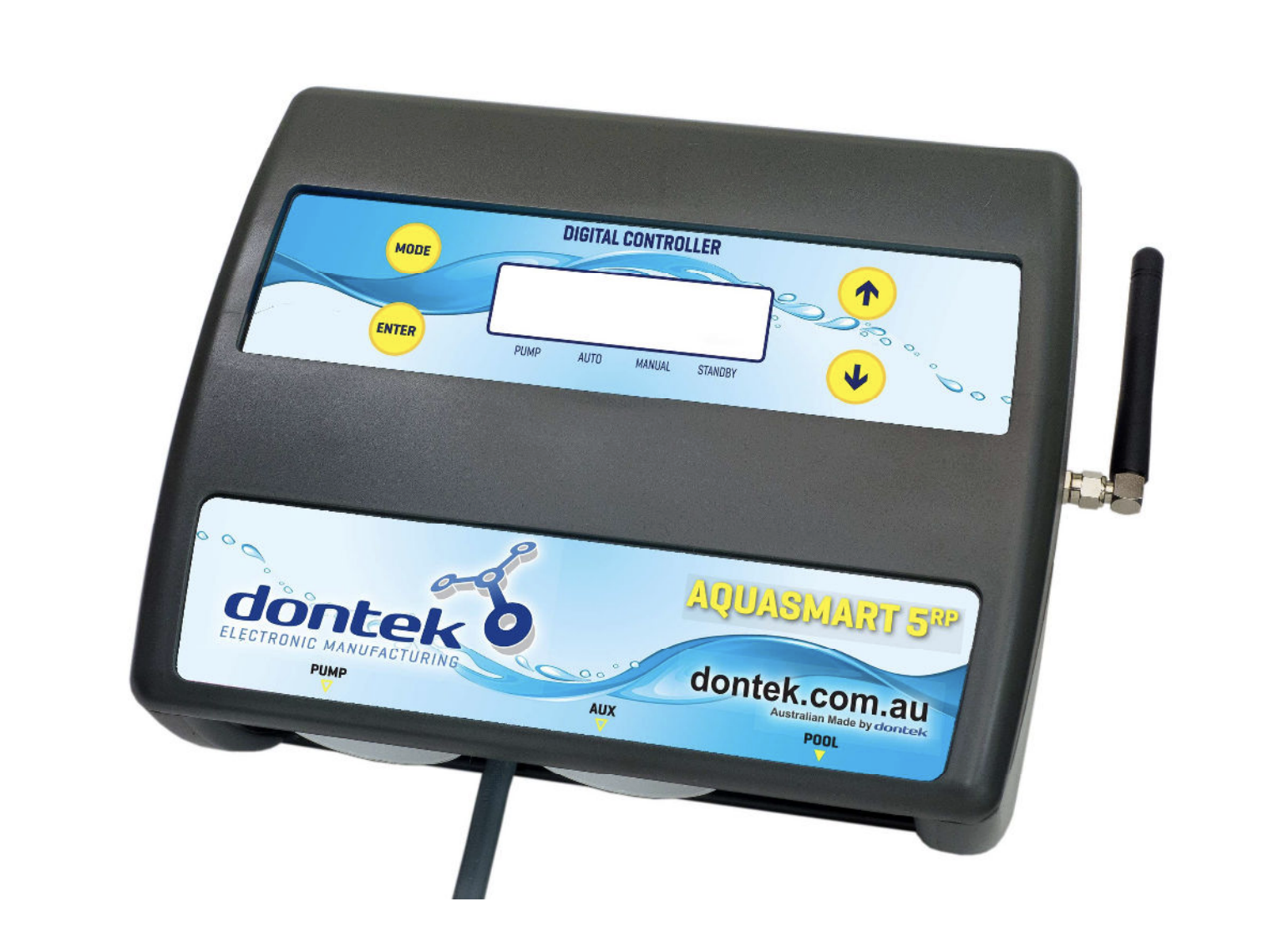
The AQUASMART 5 RP represents an advanced solution for automated solar pool heating control. Manufactured by Dontek Electronics, this premium controller features wireless roof temperature sensing powered by solar panels, eliminating the traditional need for long cable runs from controller to rooftop sensors.
Product Overview
The AQUASMART 5 RP is designed for residential solar pool heating systems, offering automatic temperature management with multiple operating modes. The standout feature is the wireless radio-frequency (RF) roof sensor system that transmits temperature data from a solar-powered unit mounted near the solar collectors, simplifying installation and improving reliability.
Key Features
Wireless RF Temperature Sensing: Solar-powered transmitter eliminates roof sensor cables, operating within a 100-metre range with no obstructions.
Multiple Operating Modes: Heating (automatic), manual override for testing, standby for off-season maintenance, and optional cooling mode.
Adjustable Temperature Control: User-programmable temperature limits with ±0.5°C hysteresis for precise pool temperature management.
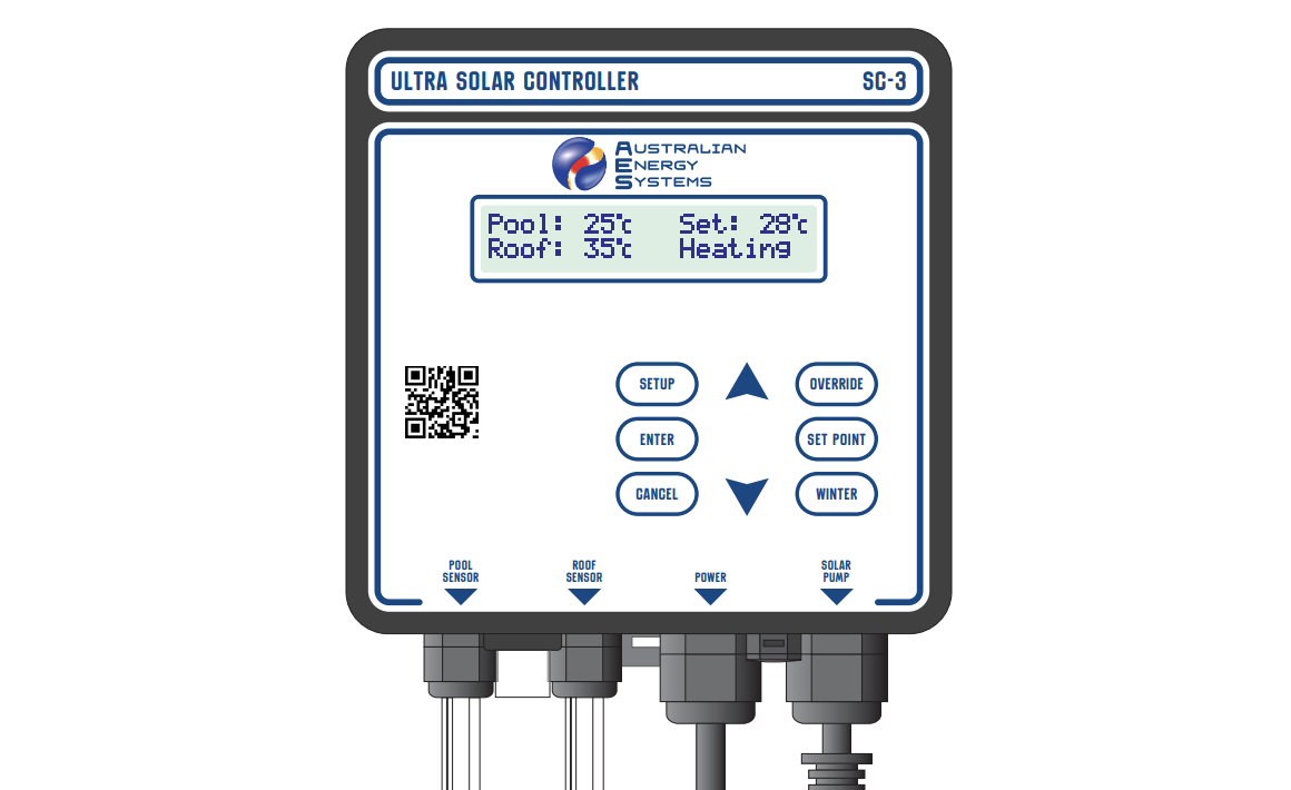
LCD Display: Clear backlit screen showing pool temperature, roof temperature, solar limit setting, pump status, and time/date.
Programmable Operating Hours: Configurable daily start and stop times (6:00-21:00) to optimise heating efficiency.
Anti-Boil Protection: Optional function prevents collector overheating when the pool reaches the target temperature.
Three-Year Warranty: Limited warranty against component failure or faulty workmanship.
Installation Requirements
Controller Mounting Location
The control box should be installed following pool equipment safety standards:
- Minimum 3 metres from the water’s edge
- Minimum 600mm above ground level
- Mounted out of direct weather where practical
- On a solid structure using the supplied mounting bracket
- Within 1.8m of GPO (power cable length limitation)
- Power must connect directly to the outlet, not an extension lead
Critical Radio Consideration: Location selection is crucial for wireless operation. The controller must be positioned where RF signals can be reliably received. Avoid mounting near other electrical equipment, inside metal enclosures, beneath pools, or behind reinforced concrete walls that may block transmission.
Pool Sensor Installation
The wired pool temperature sensor connects to the socket marked “POOL” and must be installed in the heating circuit as close to the pool as practical:
- Positioning: Install in a location out of direct sunlight, preferably on the shaded side of the plumbing
- Hole Preparation: Drill a 14.5mm hole in the side of the PVC pipe (never on top where water collects)
- Drilling Technique: Use a Dontek PD01 grinding drill or 14.0mm bit spinning counter-clockwise to minimise pipe shattering risk
- Sensor Installation: Insert the supplied grommet into the pipe, then gently push in the sensor barb
- Cable Management: Secure approximately 30cm of cable to the shaded side of the pipe to prevent ambient temperature interference through copper conductors
Wireless Roof Sensor Installation
The solar-powered RF transmitter unit mounts near the gutter line and communicates wirelessly with the controller:
Sensor Placement: The temperature probe must be fitted into a small piece of solar collector material and attached to the roof. Position within arm’s reach of the gutter edge, on a roof aspect similar to the main collector array.
Critical Installation Rules:
- Never mount on top of the main solar collector
- Avoid high points like ridge capping (causes false high readings)
- Sensor must remain unshaded throughout the day
- Solar panel (PV) must face north for maximum charging
- Antenna must point vertically upward (water ingress voids warranty if pointing down)
Transmitter Mounting: Fix the RF transmitter box to the gutter with the internal sensor cable connected to the screw-in socket inside the unit.
Site Testing Procedure
Before permanent installation, conduct a thorough RF reception test:
- Enter Test Mode: Hold DOWN button while applying power to controller
- Verify Display: Screen will show “RX TEST” when mode is active
- Monitor Reception: Roof temperature should display every 5 seconds (e.g., “TEST 32°”)
- Initial Check: Verify no missed transmissions for 30 seconds
- Extended Verification: If initial test passes, monitor for 2 minutes with no missed transmissions
- Reposition if Needed: If transmissions are missed, relocate either transmitter or controller to eliminate echo/ghosting
- Permanent Installation: Once reception is consistent, mount both units permanently
- Final Confirmation: Re-test after mounting to ensure continued reliable reception
Operating Tolerance: During normal operation, the system tolerates occasional missed transmissions. However, if more than 50 minutes elapse without successful reception, the controller displays “WAITING FOR ROOF TRANSMISSION” and cannot operate automatically.
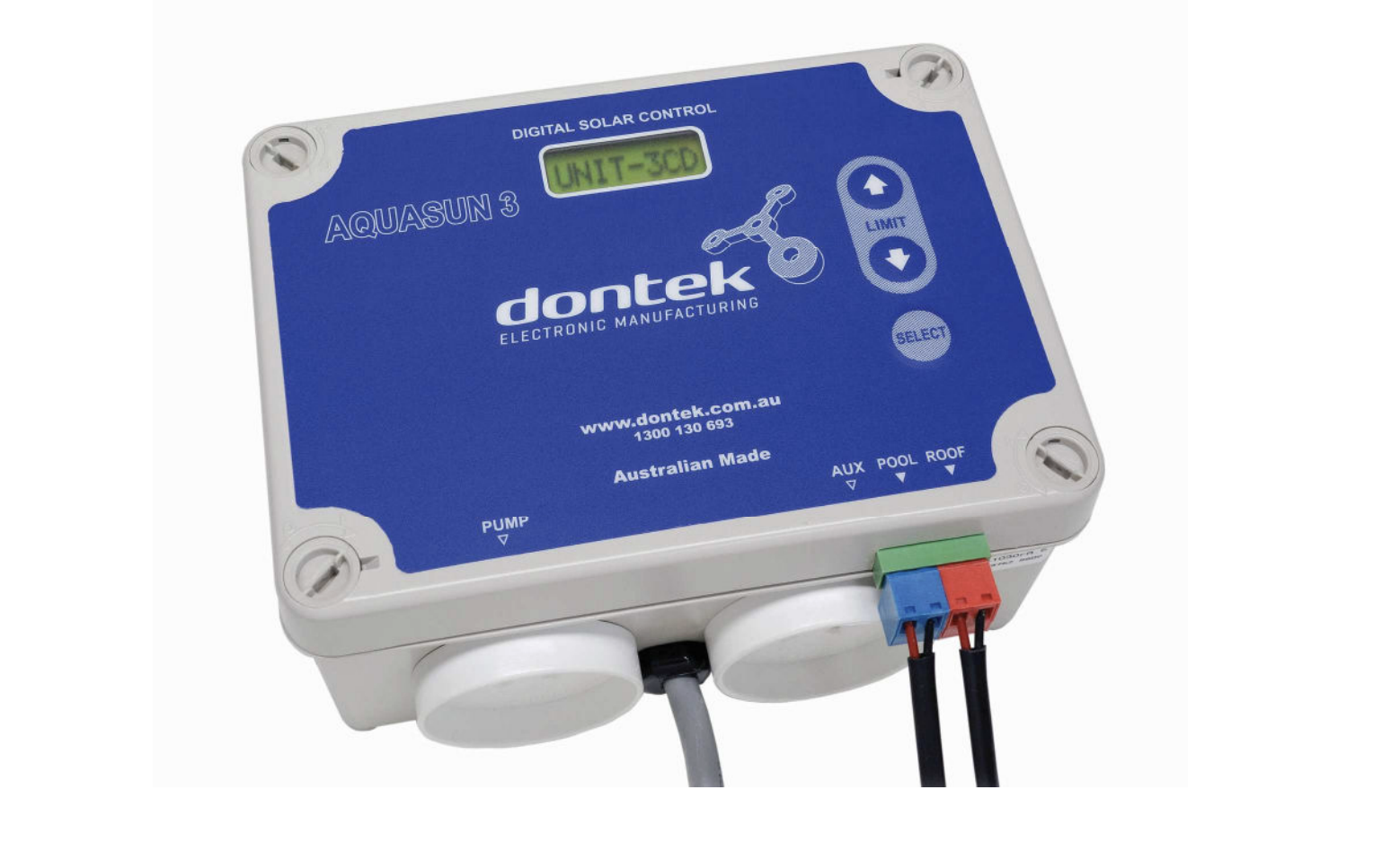
Electrical Connections
The solar pump connects to the 240V socket labelled “PUMP” with a maximum load capacity of 9.98 amps at 2,395 watts. The controller’s IP33 moisture protection rating provides splash resistance but not waterproof protection.
Operating Modes
Heating Mode (Auto)
This is the default and primary operating mode for normal pool heating. The controller continuously monitors pool and roof temperatures, automatically starting the pump when the roof temperature exceeds the pool temperature by the “RUN” differential (installer-configurable).
Operation Cycle:
- Controller compares roof and pool temperatures
- When roof temperature reaches pool + RUN differential, pump starts
- Pump continues running until roof temperature drops below pool + END differential
- System cycles as needed throughout the day to maintain target temperature
Temperature Limit Function: The controller heats until the pool reaches the set temperature limit plus 0.5°C. Heating then pauses until the pool cools by 0.5°C below the limit (actual hysteresis ±0.5°C due to rounding). This prevents unnecessary pump operation once the desired temperature is achieved.
Manual Mode
Manual mode provides pump override for system testing, particularly useful on cold or cloudy days when automatic mode wouldn’t activate. When selected, the pump starts immediately regardless of temperature conditions. The mode automatically times out after a preset period, returning to the previously selected mode.
This feature allows installers and pool owners to verify pump operation, check for leaks, and ensure the system is properly primed without waiting for suitable solar conditions.
Standby Mode
Standby mode is designed for off-season periods or when pool heating is not required. Unlike simply switching the controller off, standby mode provides important maintenance benefits:
- Pump runs for 3 minutes daily at 10:00 AM (or from when standby was selected)
- Circulates chemically treated pool water through collectors
- Prevents chemical precipitation in solar plumbing
- Maintains pump bearing lubrication and mechanical seal condition
- Reduces risk of seized pumps after extended inactivity
This minimal operation preserves system integrity without providing heating.
Optional Features
Cooling Mode: Some AQUASMART 5 RP variants include cooling capability, allowing nighttime operation to reduce pool temperature by circulating water when roof temperature is lower than pool temperature.
Anti-Boil Protection: When enabled, this function activates if roof temperature rises above the selected threshold (indicating pool has reached maximum temperature). The pump runs for 5 minutes every 15 minutes to prevent collector overheating and degradation.
Pipe Protection Mode: For installations with flooded/flat collectors, this mode requires a wetted roof sensor and adjusts operation to prevent pipe damage from thermal stress.
User Controls and Settings
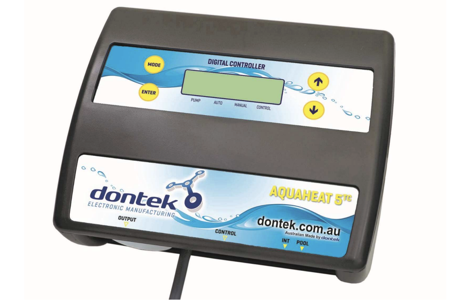
Basic Operation
MODE Button: Cycles through operating modes in sequence (Heating → Manual → Standby). Selection is automatically saved when button release is detected.
UP/DOWN Arrows: Adjust the solar temperature limit setting. Factory default is 30°C, adjustable based on desired pool temperature.
ENTER Button: First press activates LCD backlight. Pressing ENTER while backlight is active accesses the settings menu system.
Settings Menu Structure
The settings menu provides access to configuration options using UP/DOWN navigation and ENTER to select flashing items:
Clock Setting: Set current time of day for accurate scheduling and display.
LCD Backlight Timer: Configure how long the backlight remains active after button press (or select “NONE” for always-on operation).
Operating Hours: Define daily start and stop times in hourly intervals. Start time selectable from 6:00-12:00, end time from 12:00-21:00. Factory default is 12:00-12:00 (24-hour operation).
Installer Setup Menu
Advanced parameters accessible only through installer-specific menu access (press ENTER, scroll to SETTINGS, press MODE button):
RESTORE DEFAULTS: Returns all settings to factory configuration.
RUN Differential: Sets the temperature difference (roof above pool) required to start the pump. Lower values provide more aggressive heating but may cause short cycling.
END Differential: Sets the temperature difference at which the pump stops. Typically lower than RUN value to create hysteresis and prevent rapid cycling.
BOIL Temperature: Sets the threshold for anti-boil protection activation (on supported models).
PIPE PROTECTION: Enables pipe protection mode for flooded collector installations.
CAL (Calibration): Allows calibration adjustment of the pool sensor if comparison with accurate thermometer reveals offset.
ROOF SENSOR: Permits temporary use of a wired roof sensor cable if the wireless PV unit is damaged and awaiting replacement.
All menu settings automatically save and return to automatic operation if left unattended for 3 minutes.
Troubleshooting and Maintenance
Common Fault Messages
“WAITING FOR ROOF TRANSMISSION”: The controller cannot receive RF signals from the roof transmitter. This indicates:
- Transmitter out of range or obstructed
- Interference from other equipment
- Transmitter solar panel not charging (shaded or dirty)
- Transmitter malfunction
Resolution: Verify transmitter solar panel is clean and receives direct sunlight. Check antenna orientation (must be vertical). Review installation location for new sources of interference. Conduct site test procedure to verify reception.
“ROOF SENSOR DISCONNECTED”: The sensor cable is not properly connected to the transmitter screw terminals, or cable damage has occurred.
Resolution: Check all connections are firm. If cable has been extended or repaired, ensure joints are soldered and sealed with heat shrink. Replace damaged cables rather than attempting repairs if damage is suspected.
Operational Issues
Pump Not Starting Despite Good Solar Conditions: Check that mode is set to Heating (Auto), not Manual or Standby. Verify pool temperature is below the set limit. Confirm both sensors are reading correctly. Check RUN differential setting is not too high.
Pump Starts But Stops Quickly: May indicate priming failure. If pump fails to prime, it will circulate only air, causing rapid roof temperature increase detected by controller. Check pump basket is full of water, all valves are open, and no air leaks exist in suction line. Prime pump per manufacturer instructions if needed.
Higher Than Expected Roof Temperature Reading: If the controller has stopped the pump but shows unusually high roof temperature, this typically confirms pump priming failure. The sensor is reading air temperature in the collector rather than water temperature.
Maintenance Requirements
Monthly Checks:
- Verify controller display is functioning and showing current information
- Check transmitter solar panel is clean and unshaded
- Confirm antenna remains vertical
- Inspect all cable connections for corrosion or damage
Annual Inspection:
- Test all operating modes
- Verify temperature accuracy with calibrated thermometer
- Clean transmitter solar panel thoroughly
- Check for any signs of water ingress in transmitter housing
- Inspect sensor installation points for degradation
Power Interruption: The controller retains all settings and programming for 10 days during power loss. When power is restored, automatic operation resumes immediately with no user intervention required.
System Specifications
| Specification | Value |
| Power Supply | 240VAC, 50Hz |
| Pump Socket Rating | 9.98A max, 2,395W max |
| RF Range | 100m (no obstructions) |
| RF Frequency | ISM band (licence-free) |
| Transmission Interval | Every 5 seconds |
| Transmission Timeout | 50 minutes |
| Moisture Protection | IP33 |
| Power Cable Length | 1.8m (non-detachable) |
| Display Type | LCD with backlight |
| Temperature Range | Display -9°C to 99°C |
| Memory Retention | 10 days without power |
| Warranty Period | 3 years (limited) |
Advantages of Wireless Design
The AQUASMART 5 RP’s wireless RF sensor system offers several practical benefits over traditional wired installations:
Simplified Installation: Eliminates the need to run sensor cable from controller to roof, which often involves drilling through walls, navigating roof spaces, and managing long cable runs susceptible to damage.
Improved Reliability: Wired roof sensors frequently develop connection issues due to UV degradation, physical damage from roof traffic, or corrosion in connection points. The solar-powered wireless transmitter eliminates these failure points.
Flexible Controller Placement: Without the constraint of roof sensor cable length, the controller can be positioned in the most convenient location within RF range, improving access and weather protection.
Retrofit-Friendly: The wireless design makes the AQUASMART 5 RP particularly suitable for retrofitting existing solar systems where running new cables would be impractical.
Maintenance Free Power: The transmitter’s solar panel provides indefinite power without battery replacement requirements, reducing long-term maintenance costs.
Installation Best Practices
Plan RF Path: Before mounting, evaluate the RF transmission path between transmitter and controller. While 100 metres is achievable with clear line of sight, installations through multiple walls or near interference sources require more careful planning.
Test Before Permanent Mounting: The site test procedure is not optional. Permanently mounting the transmitter without testing can result in unreliable operation that may not be discovered until the first heating season.
Avoid Future Interference: Consider what equipment may be installed in the future. Variable-speed drives, pool automation systems, and other RF devices may interfere with transmission if added later.
Document Installation: Record the transmitter and controller serial numbers, installation date, and any custom settings. This information is valuable for warranty claims and future troubleshooting.
Educate Pool Owner: Ensure the pool owner understands basic operation, particularly the difference between operating modes and what fault messages indicate. This prevents service calls for non-issues like standby mode selection.
Check Local Regulations: Verify that the installation complies with local electrical codes and pool safety regulations regarding equipment placement and electrical protection.
Warranty and Support
The AQUASMART 5 RP includes a limited 3-year warranty covering component failure and faulty workmanship from the date of installation. The warranty does not cover:
- Damage from misuse or improper installation
- Power surge or lightning strike damage
- Installations not following manufacturer instructions
- On-site labour or travel costs
- Damage from corrosion or chemical exposure
Important Safety Note: If the power cord is damaged, do not use the controller. Return the complete unit to the supplier for professional repair or replacement. Never attempt to repair power cables yourself.
Faulty units should be returned initially to the purchasing dealer, who will coordinate warranty assessment and replacement. For service assistance, detailed troubleshooting guides and updated firmware information are available at www.dontek.com.au.
Conclusion
The AQUASMART 5 RP solar controller combines practical innovation with reliable pool heating automation. The wireless roof sensor design eliminates one of the most problematic aspects of traditional solar controllers whilst maintaining precise temperature control and multiple operating modes.
For pool owners, the system provides effortless automated heating with clear feedback and simple controls. For installers, the wireless design reduces installation time and eliminates many common service call causes related to sensor cable problems.
The three operating modes, adjustable temperature control, and optional anti-boil protection make the AQUASMART 5 RP suitable for diverse pool types and climates across Australia. With proper installation following the site test procedure, the system delivers years of trouble-free automated solar heating control.